- Broadcast engineering and IT related links and stuff. Maybe some music, films and other things.
Showing posts with label fibre. Show all posts
Wednesday, September 24, 2025
Extending serial (RS232/422/DMX) over long distance
Here's a little video showing how to use the Barnfind BarnMini05 to extend serial control over very long distance using wavelengths on a single mode fibre.
Wednesday, December 06, 2017
Fibre for breakfast - keeps you regular...
I've have been a terrible blogger over the last couple of months; just super-busy at work, but I have done a couple of presentations in Jigsaw24's ongoing series of Tech Breakfasts.
All the slides are here.
Tuesday, September 22, 2015
Fibre infrastructure and CWDM developments
The most interesting things I saw at IBC last week were not software updates or new 4k workflow tools (save us from "workflow tools"!) but some developments from our good friends at Barnfind.
Their current CWDM products top-out at 18-wavelengths on a single fibre, and if you need to pack more signals (synchronous broadcast; HD/SDi, MADI, AES etc OR asynchronous data; ethernet, fibre-channel etc) onto a fibre then DWDM is the answer - with a big price tag!
They showed me a prototype of their "pre-mux" product which can take six wavelengths and multiplex them onto a single SFP-wavelength; essentially it reduces the channel spacing down to 1.6nm but the upshot is that it is entirely compatible with the existing product range. You can use your current SFPs, Optical de/multiplex and single-mode cabling. You wind up with 106 usable channels on a single fibre.- They also showed me Embryonix's ST2022 video encoder/decoder pair in SFP form; this allows you to use Barnfind as your video router in and out of an IP environment - I was blown away; a complete 2022-encoder with 10gig fibre i/o from a 3G source.
Barnfind are also taking their router up to 12Gig for single-wire UHD-TV routing; this will allow much greater penetration into the 4K market and although I never thought routing ten gig ethernet was a good idea (you don't want your edit assistant assigning the backbone network traffic!) it will be important for both baseband and IP 4k.
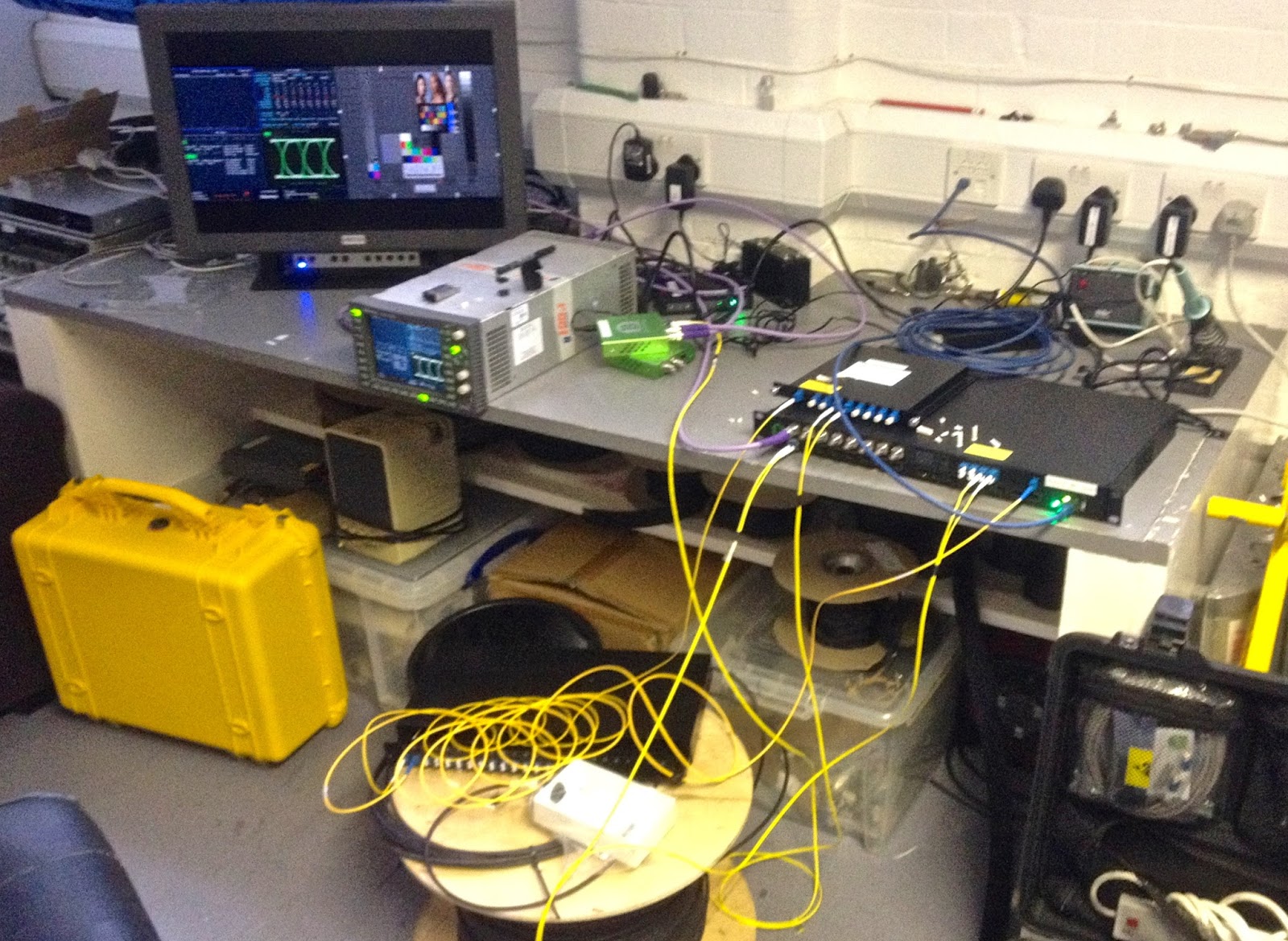
Whilst on the subject of Barnfind I have a 1350nm SFP which when in a demo chassis caused an intermittent yet repeatable fault; routing 1.5G video (1920x1080 @4:2:2) through it would cause CRC errors in only the AES packets; the signal was then sent to a BT facility line and the first MPEG-encoder it hit at the tower showed the fault by both video and audio disturbance every few seconds; I assume that is down to how that model of encoder extracted timing information. Swapping the SFP out for a new one (exactly the same model) drove the fault away but putting the existing one back re-introduced the trouble.
I am flummoxed how a format converter can reach into the SDi stream and corrupt the AES CRCs - it doesn't seem possible and so I was eager to get it back to the workshop to test it and get a bit more info. So - I have replicated the configuration as much as is possible - even down to the 1000m fibre drum we keep to hand (it's 250m of four core with the ends spliced-back on each other).
However - the thing has been on 24-7 since last week with my trusty Tek WFM7120 monitoring it waiting for any errors to show and there has been nothing! Do I trust this SFP now? I suppose if I keep it in the demo kit it will be a good test.
Friday, March 20, 2015
Reliable Avid ethernet traffic over old fibres
The first Avid Unity fibre-channel SAN I installed was in 1999 and fibre was the standard for high-speed shared storage for editing for more than a decade. However; since the introduction of MPEG4-based editing codecs which allowed Avid to offer high quality DNxHD we've been all about ethernet-attached shared storage; in Avid's case the ISIS storage products.
We have had a lots of customers who went to the expense of running OM3 (50 micron multi-mode fibre) cable only a few years ago and are now cheesed-off that they need to flood their facility with cat6 or 7 because the rough-old cat5e they have doesn't work reliably for gigabit. So; the obvious choice is to use that fibre which had bags of bandwidth for ethernet but until very recently that was not an approved configuration by Avid. Recently they have tested Allied Telesis media converters and given a cautious thumbs-up. BUT, they are very expensive (a few hundred quid per workstation, so back to running new cable), but I had a quick chat with the guys at Comtec about the house-brand they supply which uses the same chipset.
Neal Kemsley kindly ran Avid's PathDiag tool before and after and these little cheapies seem entirely transparent. Here's what he fed back to me;
"Windows ISIS client attached directly to a Dell N3048 switch running Pathdiag in an “Unlimited” Writes then Read PathDiag test cycle targeting an ISIS Workspace (the term used by Avid for their storage volume – the same as Unity). Unlimited means that the test attempts to saturate the channel between the ISIS client and is a good indicator of the upper limits of the potential connection between the client and the storage. In this case it is a 1 Gbit copper connection to the switch, and an optical 10 Gbit connection between the switch and three ISIS 5500 storage chassis. As you can see we are getting a result north of 100 MBs per second – yes that is MegaBytes – not bad for a 1 Gbit path! (Not too shabby as they say in Boston!)"
"This one shows the same test parameters but with the client attached to
the switch using the media converter pair in circuit. Note that the test
results are really similar perhaps with some minor variation in the
upper reaches of the test during the write cycle but nothing serious.
The overall speeds achieved during the tests are essentially the same as
a direct connection and there are no errors displayed.Note that the graph pattern drawn by the test is relatively clean showing very little spiking or variation and clean transitions between the Write tests and the Read test cycle. Note also that no errors are seen in the error count on the right side."
"We would want to run the test for several hours to draw conclusions on this but these results are very promising. We would probably want to also change the Transfer Size parameter of the test up and down to emulate different editor timeline characteristics. Smaller values are used to emulate working with heavily compressed material, the current setting being used to emulate working with DNxHD material, and larger values can be selected to emulate working with uncompressed HD and UHD material."
"To emulate working with several streams of data in a timeline this shows four independent PathDiag test sessions running simultaneously with the Media Converters in circuit. In this case rather than working with unlimited tests, I set the Transfer Rate parameter to 25 MB/sec and allowed the tests to cycle for 30 minutes. Notice for results graphed in these tests the individual tests are interacting somewhat – see that the top value levels are becoming choppy and castelated somewhat as each test competes for throughput. Since the tests in aggregate are pushing the maximum limit of the channel (if all four tests happen to be writing or reading simultaneously, the overall write or read bandwidth should around 100 MB/sec) this interaction is quite normal and will get worse if similar test were being run on further clients in the ISIS environment as each client competes for access to the storage."
Friday, October 24, 2014
Fibre 102; CWDM & encircled flux - The Engineer's Bench Podcast
Hugh and Phil talk about optical multiplexing as well as new methods for
accurately testing fibre cables. A few tips on basic fibre cleaning as
well.
Find it on iTunes, vanilla RSS, YouTube or the show notes website.
Wednesday, September 10, 2014
Ongoing Barnfind notes
As I get more familiar with Barnfind's products I need to make a note of some of their gotchas!
The Tx and Rx lights on all SFP ports are not data lights, rather they are clock lights and as such only light when you're dealing with synchronous broadcast signals - HD/SDi, MADI, AES etc.
The CWDM multiplexer/de-multiplexer (they are exactly the same unit!) works both ways and if you have signals going bi-directionally on a fibre each port is an input or an output; that takes a bit of getting your head around!
-
In a similar vein the wavelength quoted on SFPs (1350nM in this image) only really applies to the transmitted signal; SFPs are "colourblind" - they don't mind what wavelength they receive. So, once a signal leaves the CDWM de/multiplexer you can take it into any of your SFPs for input to the crosspoint router - again, it's not particularly intuitive as we're used to "tuning" or "demultiplexing" other signals to the frequency they'll be used at.
- The BarnStudio software; the manual says that it comes set up hard-set to a 192.168.0.1 address; our didn't, it was setup for DHCP and since it doesn't respond to multicast PINGs it took me a while to figure this out.
- If you are routing ethernet out to the multiplexer it is always directional (i.e. it takes up the in and out of an SFP and needs two ports on the multiplexer).
- See note 1 above (no activity lights) for ethernet.
- If you're using the same machine to drive BarnStudio and test an ethernet connection (by sending it via an ethernet SFP -> fibre -> multiplexer -> BarnMini -> SFP -> ethernet) you run the risk of an ethernet loop and subsequent broadcast-storm! Wesley & I suffered this and couldn't figure out why the entire workshop network was down. Much better to use your rucksack router & a RaspberryPi as a separate test network.
- The BarnStudio software - although good, is a tad hard to read initially as if you give the ins and outs proper names they re-order alphabetically rather than in order of the SFPs and BNCs. Just remember - inputs are down the left axis and outputs are along the top (most things are present in both).
Monday, August 25, 2014
Barnfind's high-speed data router and optical CWDM for TV infrastructure
I've been a very slack blogger over the last five weeks due to work (installations, running training, getting trained!) and holiday (splendid). I spent a few days last week in Norway as the guest of Barnfind in Sandefjord.
Norway seems to be a lovely country if not a tad expensive (£24 for a round of three pints). Barnfind are a small company whose engineers used to be with Nevion - you've probably come across their VikinX range of HD/SDi and other facilities routers.
I had a long Skype chat with Barnfind a month ago and kind of 'got' their range. It's not a one-for-one replacement for any other specific products rather a platform that nicely ties together all digital signals within a facility; synchronous (SDi, MADI, AES, etc) and asynchronous (ethernet - copper & fibre, fibre-channel). They also make CWDM very do'able in a broadcast environment. As we move towards an entire IP infrastructure these are the kind of platforms that allow an easy transition.
The basic product (the BarnOne BTF1-01) is a 32x32 generic data router and 16 bi-directional SFP ports. The SFPs can be any MSA-compliant units but Barnfind manufacture their own at very reasonable costs (much less than Cisco!). You could insert Ethernet, SDi i/o, fibre or any of around 150 variations they offer. This allows you to route SDi in and out over fibre, insert AES into an SDi stream, convert ethernet to/from fibre etc etc.
3G HD/SDi input/output SFP
Clearly some signal types don't sensibly convert; routing an SDi stream to a fibre channel-equipped port won't replace an HP workstation running Avid! But where is does make sense everything is taken care of for you. In the case of all video signals (composite, SDi and HDMI are all supported) the signal is converted in the SFP to 3G SDi before it is passed to the 32x32 router.
The BarnOne range extends to several variations - the lower board which carries the router and the first sixteen ports can be joined by two upper boards carrying BNCs, more SFP holes or (more interestingly) CWDM fibre modules. Essentially having BNCs on an upper board allows you to avoid SDi SFPs (it's marginally cheaper to do it on an 8-way board than an extra 8-holes with video-SFPs).
The other end of the link could be easily served by their BarnMini units - essentially replacing Blackmagic or AJA converters but integrating very nicely with the BarnOne. For less than £400 you can get either two BNCs with an SFP hole or two SFPs.
The whole thing makes sense when you realise that all the signal intelligence is in the SFPs - the dual-port BarnMini can do anything that makes sense; maybe you need to route some ethernet coming in on single-mode fibre and send it out over existing multi-mode cable. Again, AES, SDi, MADI as well as all fibre and copper networking are supported.
Before I start banging on about Course Wave Division Multiplexing it is worth including a photo of the insides of a BarnOne so you can see the control card they use.
That's right! It's a RaspberryPi! When re-invent the wheel; they claim they tested a few Linux SOC boards and found the humble Pi to be the most reliable and they make use of the watchdog timer to ensure it's always listening for config updates. Their BarnStudio software not only allows you to configure the system (including all the monitoring via SNMP) but you can also control the router. They also support several manufacturers generic control panels if that's what's needed.
CWDM
Single mode cable (more often than not) is used to carry a network feed, a 3G video feed or some other data. We quote wavelengths for fibre (typically 1310nM) rather than frequency and so often forget that the sidebands of the signal we put down a fibre are tiny relative to the centre frequency. 1400nM of wavelength is around 200Thz (yes, 200 x 10^12 Hz!) which makes the 4.5Ghz bandwidth of the best-quality HD video coax look very modest. So, we could divide up the single-mode range into many wavelengths and use each for a different purpose; a bit like the radio stations on the VHF band.
These are the standard wavelengths for CWDM working; sixteen channels and by convention the two colours run in different directions (SDi input/output or ethernet Tx and Rx for example). This allows you to have SFPs that put the signal they send/receive onto specific wavelengths. Then, with a simple passive optical splitter/combiner (which is all a CWDM multiplexer is). With all this in place you can use your Banrfind kit to multiplex sixteen functions in and out of a single 9/125u fibre. If that's all you have between premises then this is a lifesaver. The multiplexers are in the £400 range.
We opened one up last week and it was a thing of beauty; all passive optical engineering with tiny dichroic filters. So, by careful planning you could send multiple SDi signals, ethernet, fibre channel and other things to and from a remote site over a single strand of mono-mode fibre. It could be up to 80kms away.
There is a further development of the multiplexing technology called Dense Wave Division Multiplexing - DWDM which allows up to 192 channels and very far distances (by the use of Eridium-doped optical amplifier - but in the case of Barnfind (and other manufacturers) the cost of DWDM vs CWDM is fivefold!
The BTF1-07 is the box I've ordered as my demo unit; it has sixteen SFP holes, eight bi-directional BNCs as well as a CWDM multiplexer.
Labels:
barnfind,
facilities,
fibre,
HDMI,
infrastructure,
video
Saturday, June 28, 2014
Measuring fibre cabling and the problem of encircled flux loss
Last week I went on a very interesting training day courtesy of Nexans - data cable & parts supplier. I went looking forward to learning all about the new standards surrounding catagory-8 cabling for 40 and 56 Gigabit ethernet (a massive 1600Mhz of bandwidth down a twisted pair cable!) and the new GG45 connector; but those things will have to wait for another blog post! The thing that really tickled my fancy is the new standard for measuring the response of multi-mode fibre.
Multi-mode fibre works in a fundamentally different fashion to single mode (they are as different as twisted-pair and coaxial copper cable; but they look very similair). If you want a bit of a primer on fibre then Hugh & I did an episode of The Engineer's Bench a couple of years ago on the subject.
As we've gone from one-gig to greater than 10Gigbits/sec in OM3 and OM4 cable and engineers have often noted the lack of consistency between different manufacturers light-source testers. You might get as much as 0.5dB of difference between say an Owl and a JDSU calibrated light source and detector. We typically use a 20dB(m) laser at 850nM to test OM3 and we always just deliver the loss figres to the client, but it would be good to know if your absolute reading is of any use at all?
Well, the answer is that LED or VCSEL (Vertical-cavity surface-emitting laser) will tend to "overfill" the fibre and high-order modes of light travel (to a degree) down the cladding of the cable.
Launch conditions correspond to how optical power is launched into the fiber core when measuring fiber attenuation. Ideal launch conditions should occur if the light is distributed through the whole fiber core.
Transmission of Light in Multimode Fiber in Underfilled Conditions
Transmission of Light in Multimode Fiber in Overfilled Conditions
An overfilled launch condition occurs when the launch spot size and angular distribution are larger than the fiber core (for example, when the source is a light-emitting diode [LED]). Incident light that falls outside the fiber core is lost as well as light that is at angles greater than the angle of acceptance for the fiber core. Light sources affect attenuation measurements such that one that underfills the fiber exhibits a lower attenuation value than the actual, whereas one that overfills the fiber exhibits a higher attenuation value than the actual.
The new parameter covered in the IEC 61280-4-1 Ed2 standard from June 2009 is known as Encircled Flux (EF), which is related to distribution of power in the fiber core and also the launch spot size (radius) and angular distribution.
All the manufacturers are producing EF-compliant testers so you don't need to worry about inaccurate reading due to these high-order modes, but for now there are some suggestions.
Multimode launch cables allow for the signal to achieve modal equilibrium, but it does not ensure test equipment will be EF-compliant based on the IEC 61280-4-1 standard.
Multimode launch cables are used to reveal the insertion loss and reflectance of the near-end connection to the link under OTDR test. They also reduce the impact of possible fiber anomalies near the light source on the test.
If the fiber is overfilled, high-order mode power loss can significantly affect measurement results. Fiber mandrels that act as “low-pass mode filters” can eliminate power in high-order modes. It effectively eliminates all loosely coupled modes that are generated by an overfilled light source while it passes tightly coupled modes on with little or no attenuation. This solution does not make test equipment EF-compliant.
Mode conditioning patch cords reduce the impact of differential mode delay on transmission reliability in Gigabit Ethernet applications, such as 1000Base-LX. They also properly propagate the laser VCSEL light along a multimode fiber. This solution does not make test equipment EF-compliant
Friday, January 24, 2014
A lie can travel half way around the world while the truth is putting on its shoes.
Not that Mark Twain knew much about fibre optic cable. If he did he'd realise that he was only talking about seventy milliseconds...!
Last week I came across the following from the Argosy website;
I often have to provide proposals and quotations in response to customer's tender documents and in the last six months I have seen three such tenders specifying tight-buffered fibre for their internal networks. When I push their staff engineers for a justification they "um and err" and are easily persuaded to do the right thing (i.e. use spliced loose-tube fibre). If you need to read up then I've written a few things in the past.
Last week I came across the following from the Argosy website;
Tight buffered cables are intended for indoor applications. They are more hardwareing than loose-tube cable, as such they are well suited for long indoor LAN connections, burial or complete even submersion in water. Tight buffered cables have a special two-layer coating. The first layer is plastic, the other a waterproof acrylate.I wonder if this mis-information is their doing?
Tuesday, December 17, 2013
Photons vs. Electrons
At ten gigabits ethernet over copper cable really struggles. Everything has to be just right and even well terminated twisted pair cable is on the hairy-edge.
On the job that I've just finished had a lot of fibre and copper data and the time to test (on a per circuit basis) is much higher for copper than fibre. With OM3 fibres so long as you have an acceptable sub-3dBs of attenuation at 850nM ten gigs is a doddle. We had to re-terminate maybe half a dozen circuits and using our INNO core-alignment splicer it takes no time. On the other hand getting the copper data cables right is a mission with Near-end cross-talk, alien cross-talk and return loss all having the be measured across four pairs. The output (above) is from our Fluke DTX-1800 analyser.
As an aside, one of the freelancers I use a lot showed me a brilliant trick with fibre panels); the BT standard for core-order involves having the coloured and striped cores 12 couplers away from each other in a 24-port panel. The better way is to put the coloured and striped cores next to each other in the same duplex pair so that if you make a mistake it's easily rectified at test-time.
Thursday, April 11, 2013
Beware the fibre contamination!
These are two pictures taken down my hand-held fibre microscope - you can see the core and buffer of two examples of fibres that were spliced maybe three months ago in a new building. I suspect builder/decorator dust contamination and even though they have had their cover-pieces on they aren't air-tight and so we're now looking at an extra 0.2dBs of loss on those circuits.

Not a whole hill of beans, but worth noting.
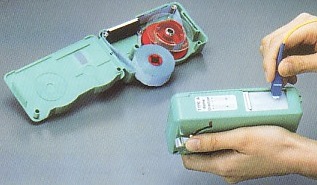
It is jolly hard to position and focus an iPhone over the eyepiece, but here is an image of what a new, uncontaminated fibre pigtail looks like (these are all multi-mod OM3 BTW). Aside from the JDSU microscope I also carry a Cletop cleaner when I'm on fibre mission. It's a small cleaner with a replaceable cartridge that allows you to swipe the end of the patch cord or pigtail with a fresh piece of dry-clean, lint-free material and it removes even stubborn stains.
Sunday, November 04, 2012
Cladding vs Core Alignment fusion splicers
For seven years we've been using Tritec Fase II fusion splicers; we have two kits composing the splicers themselves (camera or microscope inspection), clevers and finishing ovens for the splice-protectors. If you're in the business of bespoke fibre then fusion splicing really is the only way to go as you get superior performance in termination and you can base infrastructure entirely on loose-tube multi-core cable (tight-buffered cable is really only suitable for use within cabinets or at most between cabinets - it isn't man enough for running in voids and risers).
Anyway, the Tritecs have been solid workhorses clocking up many thousands of terminations between them and we've been entirely happy. In 2004 and then again in 2007 when we upgraded them they were the best sub £10k machines.
The only thing you could criticise them for is that they are "cladding alignment splicers" - they rely on the diameter of the cladding being correct (125 microns, fact fans!) and the core being correctly positioned within the fibre. The guys at Tritec tell me this is a non-problem as contemporary fibre optic stock is always spot on - ten years ago, not so much, but for now it's a problem that's solved and it is fair to say we have seen very little badly made fibre since we started; and that's many hundreds of kilometers of fibre cable!
The other side of the coin is the newer style of fibre machines called "core alignment splicers" where two cameras set at 90 degrees examine the cleaved ends of the fibres and the software dynamically aligned the ends and dried the splicing arc. The machine is then able to illuminate the join and make an estimation of the loss across the join. Fujikoura were the pioneers in this field in the mid-noughties with machines like the FSM-series costing more than £30k - clearly you'd have to do a lot of fibre work to pay off one of those! Guys who use both types a lot reckon that core-alignment machines allow you to work about twice as fast as the machine produces a much greater consistency of good splices and doesn't rely on the operator to maintain precise splice measurements. Ask any wireman about the 'fibre-blindness' that sets in around 15:00 each day; you just need to walk away and forget about squinting down a microscope for an hour or so; these are very small measurements after all!
So, we've just splashed out on an INNO IFS-10 which gets really good crits when compared to the current FSM-60 machine from Fujikura. We're going to take it on a big job we're just starting and so I'll get a good feel for it.
Here is an excellent "torture test" video of the machine in action.
Friday, May 11, 2012
HD/SDi over fibre and SMPTE 297M (2006)
I've recently installed an NVision 8144 router at a large facility and some of the output cards are for fibre - dual LCs on each SFP with 3G video conforming to SMPTE 297M (SDi over single mode fibre). Very nice.
Over the last couple of years I've put in a load of the little Black Magic fibre transceivers and although they perform admirably (only had to replace one due to it being roughly handled by an OB rigger!) but I couldn't quite bring myself to believe that the mighty Blackmagic would conform to the same spec! They really are built to budget (and excellent for it). However, I had a situation where my choice was to buy the Miranda fibre receivers (at a grand a piece) OR use the half dozen BMs I already had. To my surprise the Blackmagics worked just fine. Maybe SMPTE compliance does mean something, in the case of fibre I assumed manufacturers would juts vary too much, but I suppose SDi over copper is universal, so why not over glass as well?
Thursday, January 26, 2012
Phil & Hugh's first podcast - Fibre 101; what every broadcast engineer should know
I've been bugging various industry friends to join me in an engineer's focused podcast for a few years now. Only my pal Hugh Waters (@hugh_waters on Twitter) stepped up and we have a whole series planned in this format.
Coming soon; Mains & Electrical Safety as well as TV Colourimetry.
Friday, September 16, 2011
Monday, June 07, 2010
2010 update for Optical cabling specification for fibre‐channel SANs
Root6 has supplied many thousands of terabytes of fibre‐channel storage over the last decade and has much experience in the area of bespoke optical cabling. We are often asked to audit existing installations and the following notes are our recommendations for customers who want to provide their own cabling and not make use of our Systems Integration services.
- Grade of cable ‐ All current models of film and video SANs make use of multimode connection. OM3 cable is increasingly the preferred grade (50 micron laser-optimised glass as opposed to OM1 & 2’s 62.5 micron VCSEL‐optimised glass in accordance with ISO‐11801) and since current configurations are 4 gigabit (moving to 8 gigabit) more attention needs to paid to circuit loss than 1 gigabit (the standard when OM1 was introduced). Mixing OM1 and OM3 should be avoided because of the 2.5dBs of loss when going between dissimilar core sizes (62.5 vs 50 microns). In the case of an existing OM1 installation thought should be given to staying with that standard or migrating to the newer OM3.
- Bandwidth ‐ Whereas 1 gigabit traffic will tolerate up to 8dBs of loss we are now dealing with SANs that demand at least two octaves more bandwidth and so best practise says that we now expect no more than 3dBs of loss on a SAN circuit.
- Style of cable ‐ Although tight‐buffered cable is easy to install it is never optimal for long runs. For interconnection between equipment within a cabinet it is appropriate and between cabinets if run in protection – Copex etc. For inter‐area runs a loose‐tube cable is the best solution as it is an order of magnitude more robust and although has an slightly larger install‐time cost has a much lower TCO.
- Connectors ‐ All contemporary host‐bus adaptors and fibre‐switches terminate runs in the LC connector. If existing cables are terminated in legacy SC or ST connectors they should either be re‐terminated or re‐run as adaptors introduce signal loss. SC or ST patch panels are fine so long as run‐out cables are SC‐LC (to equipment) as appropriate.
- Testing – We will ascertain if circuits are suitable for proposed SAN deployment by illuminating them with a calibrated laser tester (850nM wavelength, ‐19dB(m) signal) and measuring circuit loss – these results will be provided to the customer.
Monday, June 15, 2009
Never use second hand fibre parts!
We include the following footnote on all of our quotes;
Customer sourced components - we appreciate that you may be able to source and free-issue parts that cost less at purchase time than we have quoted. However, we will stand by the quality and usability of components we supply. In our experience we have come across customer-supplied parts that not only prove less reliable but take much longer to install. In these cases we will have to bill for any excess wiring days caused by free-issued parts.
We did a job a few months ago where the customer insisted on supplying fibre pigtails and splice-protectors. The pigtails (OM1 LC-ends in case you wondered) were of a very poor quality and took many goes to splice properly. In the end we disposed of them and used our own stock (including the splice protectors). However - we hung onto the protectors (they looked fine) and used them on a job last week. When we fired up the calibrated laser tester (-19dB(m) at 850nM in case you wondered!) we found we were getting >20dBs of loss on each circuit. It turns out the girth of the protectors was too big for the splice-bridges and so the increased pressure on the fibre-joint meant the junction was compromised. We had to re-do ten desks worth of duplex wallboxes.
The name of this purveyor of sub-standard fibre parts that have bitten us in the backside twice now? See here!
Wednesday, April 29, 2009
Telcos and dark fibre
My institute's magazine is superb - unlike most industry/free rags it is readable and reminds me of how good Scientific American was in the eighties. One of the best articles last week was on the amount of dark fibre there is in the world. The link (above) is to the article;

This diagram is missed out of the HTML version of the article.
The telecommunications industry built too much fibre-optic network capacity during the 1990s. Companies such as KPNQwest, FLAG, Global Crossing and Tyco borrowed too much money and laid too much fibre, and suffered the consequences. Is that over-capacity still present? It’s not clear.
This diagram is missed out of the HTML version of the article.
Wednesday, October 01, 2008
Fibre patch cords protected with Copex
Tuesday, February 26, 2008
Single mode fibre
Anyhow - some things we discovered about single-mode over our usual multi-mode are;
- For loose tube cable you really can't tell the difference between the skinny 9-micron and the relatively fat 62.5 micron fibres because the cladding on the glass is the same width - 125 microns (see the diagram). In fact, when you prepare the ends and get them into the fusion splicer you are hard-pushed to see the difference.
- For testing you need to use a mono-mode light source and detector and the appropriate test leads. Thankfully Darren at DIS sorted me out with his tester. I'm going to look into buying one if we do more single-mode.
- The Tritec Fase-2 splicers that we use have a mono-mode config that runs the laser cooler so that the little centre-core isn't blown away by a beam intended for the bigger cores.
For a quick explanation of mono-mode fibre see the Wikipedia article (link in the title).
Subscribe to:
Posts (Atom)