Tuesday, September 22, 2015

Fibre infrastructure and CWDM developments

The most interesting things I saw at IBC last week were not software updates or new 4k workflow tools (save us from "workflow tools"!) but some developments from our good friends at Barnfind
Their current CWDM products top-out at 18-wavelengths on a single fibre, and if you need to pack more signals (synchronous broadcast; HD/SDi, MADI, AES etc OR asynchronous data; ethernet, fibre-channel etc) onto a fibre then DWDM is the answer - with a big price tag!

  • They showed me a prototype of their "pre-mux" product which can take six wavelengths and multiplex them onto a single SFP-wavelength; essentially it reduces the channel spacing down to 1.6nm but the upshot is that it is entirely compatible with the existing product range. You can use your current SFPs, Optical de/multiplex and single-mode cabling. You wind up with 106 usable channels on a single fibre.
  • They also showed me Embryonix's ST2022 video encoder/decoder pair in SFP form; this allows you to use Barnfind as your video router in and out of an IP environment - I was blown away; a complete 2022-encoder with 10gig fibre i/o from a 3G source. 
  • Barnfind are also taking their router up to 12Gig for single-wire UHD-TV routing; this will allow much greater penetration into the 4K market and although I never thought routing ten gig ethernet was a good idea (you don't want your edit assistant assigning the backbone network traffic!) it will be important for both baseband and IP 4k.

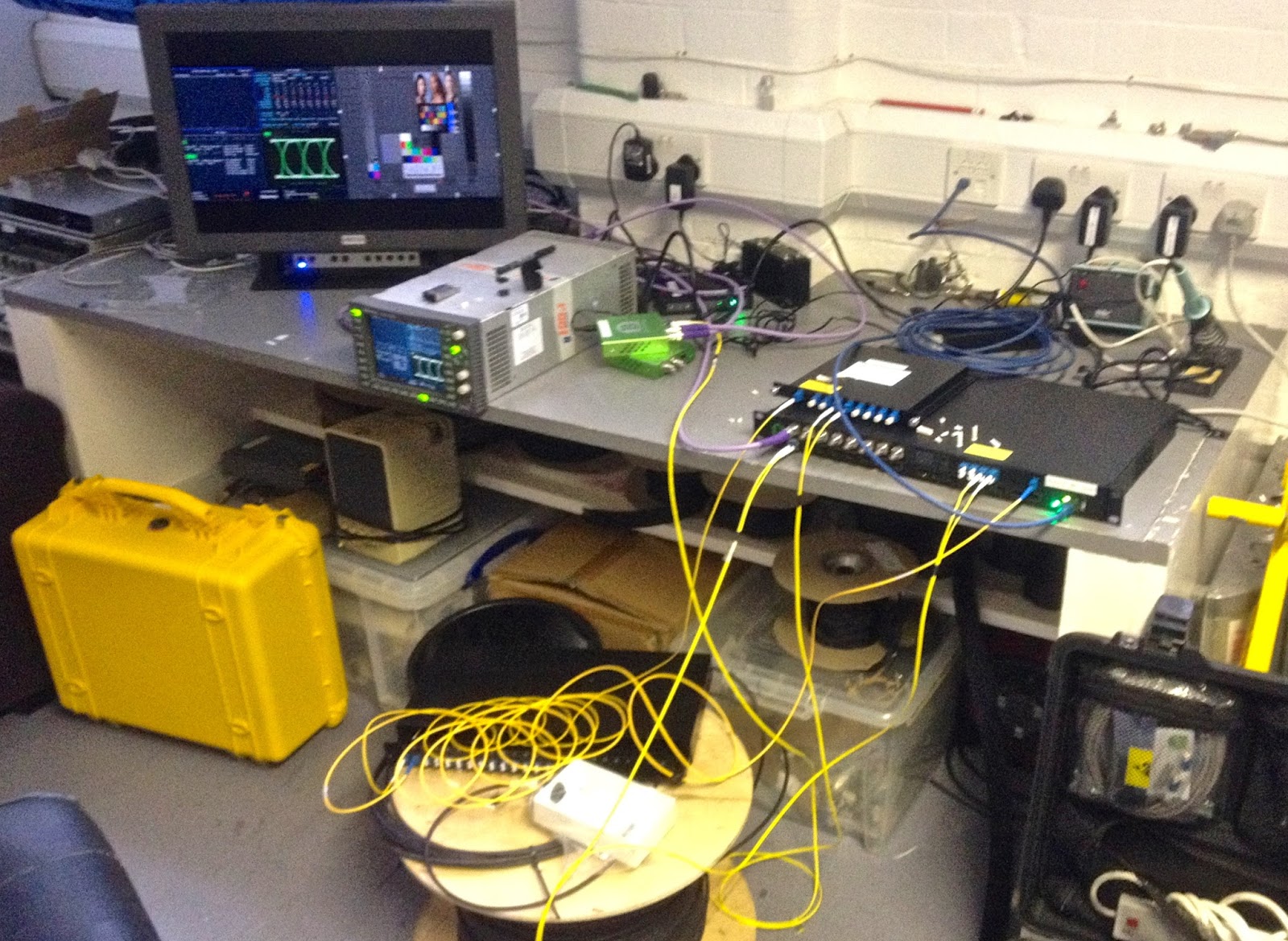
Whilst on the subject of Barnfind I have a 1350nm SFP which when in a demo chassis caused an intermittent yet repeatable fault; routing 1.5G video (1920x1080 @4:2:2) through it would cause CRC errors in only the AES packets; the signal was then sent to a BT facility line and the first MPEG-encoder it hit at the tower showed the fault by both video and audio disturbance every few seconds; I assume that is down to how that model of encoder extracted timing information. Swapping the SFP out for a new one (exactly the same model) drove the fault away but putting the existing one back re-introduced the trouble.
I am flummoxed how a format converter can reach into the SDi stream and corrupt the AES CRCs - it doesn't seem possible and so I was eager to get it back to the workshop to test it and get a bit more info. So - I have replicated the configuration as much as is possible - even down to the 1000m fibre drum we keep to hand (it's 250m of four core with the ends spliced-back on each other). 
However - the thing has been on 24-7 since last week with my trusty Tek WFM7120 monitoring it waiting for any errors to show and there has been nothing! Do I trust this SFP now? I suppose if I keep it in the demo kit it will be a good test.


Monday, September 21, 2015

"Physics is the only real science; The rest are just stamp collecting..."

You may know this quote by Ernest Rutherford and although biologists and chemists would maybe argue, all scientific people, when they get down to it, know exactly what he meant. We just happen to have given a different name to the physics of living things or the physics of chemical reactions. It's where pseudo-science (Marxism, homeopathy, NLP, Intelligent Design, horoscopes, etc etc etc.) will always show their true colours by not subscribing to the empirical method and falsifiability.

I can recall my first occasion of being aware of physics; aged seven my Dad and I had just watched "The Dam Busters" on TV and decided to build a model of the Möhne Dam out of Mechano. The final touch was two motor-driven gun-turrets powered off a 4.5v bike-lamp battery. Initially the two small motors span too fast to be convincing but my Dad showed me how rather than having two wires going to each motor we could take just one from the +ve terminal of the battery, connect the -ve terminal to the metalwork and earth the 2nd terminal of the two motors. Now, aside from providing an illustration of how car electrics work the two turrets also span a bit slower and my Dad explained that it was down to the resistance through the joins in the strips of Mechano. I understood voltage and (maybe) current at the time, but resistance to current was new and I realised that there were things going on that I didn't yet understand but I needed to!

Spin forward ten years and I was just starting a degree in physics, the very first lecture I attended had a great illustration of how poor our instinct is for all this stuff. The lecturer put up a graph with size on the X-axis (ranging from the diameter of a hydrogen nucleus to the width of the observable universe - suffice to say it was a logarithmic scale!) and velocity on the Y-axis (stationary all the way up to C - 3 x 10⁸ ms-1, the speed of light - the fastest anything can go; God's speed-limit if you will). He then drew on a box which represented most people's experience;
  • Smallest thing; for most people it's the width of a human hair or similar. I look down a microscope often to inspect fibre optic cable, so maybe for me it's a couple of orders of magnitude smaller; 10-5m
  • Largest thing; maybe all that you can see from a high mountain - 1010m2
  • Slowest thing; me in bed! 
  • Fastest thing; traveling in a modern jet liner - 300 ms-1
When you look at that box on the whole graph you realise how poor our experience is against the whole of creation and how you should perhaps trust the numbers rather than your own intuition.
So, physics is hard from a gut-feeling point of view. I changed degrees at the end of my first year to maths & programming but never lost the love of physics. Here are a few things that have helped me along the way.
So, just to stay with the popular science, I heard a great podcast in the "How to be amazing" series with Brian Greene; if you need a bit of a jump-start with your physics then he's your man!

Tuesday, August 25, 2015

Electrical Safety and Best Practise 101 - course notes

I'm off delivering my day-long mains course tomorrow at the University of Hertfordshire. You can grab my notes.

A lot of this has been covered in past episodes of my video podcast.

17th Edition, 3rd Rev.

Saturday, July 25, 2015

The Engineer's Bench podcast - "KVM-over-IP and Data Encryption"

Hugh and Phil talk about KVM-over-IP systems with particular reference to Teradici and Phil's favourite manufacturer Amulet Hotkey. They also go over the basics of encryption with symmetric and public-key crypto.


Find it on iTunes, vanilla RSS, YouTube or the show notes website.

Wednesday, July 22, 2015

Typical edit suite monitor calibration; some traps for young players

I spent the morning in a very typical Soho edit room with a JVC DT-V24-series LED-backlit LCD as the "front of house" monitor and an LG LED-backlit LCD as the client display.
It's quite easy to get the JVC looking right - BBC style 6504k for Rec.709; I've waffled on about this a lot in the past, but I had some new encounters (due in some small part to the new version of ChromaSurf; the software I use with the Klein K10A probe).
  • The Klien is a fast photometer, able to make a reading in around a second; this has huge implications for LUT building and it's why when using LightSpaceCMS you can profile a 17-point LUT in less than two hours. Older probes that can take ten seconds when coupled with something like SpectraCAL (which does not have a proper colour-engine, it essentially halves the difference every time is sees a bad colour match) might have your waiting more than a day for the same LUT profile. Being such a fast probe means that in the current release of their software you can do a 32-sample read of very low (i.e. noisey) blacks and get a reasonable figure. 
  • Just because you can read down at sub 1Cd/m2 doesn't mean you should! With LCDs when you get to sub 5% black you actually see more of the colour of the backlight leaking around those little thin-film transistor pixels. This is why I tend to calibrate black level ("Bias" in Sony-speak) around 15% to make sure I'm getting a real read from the pixels.
  • Even if a domestic display claims to have a Rec.709 mode don't believe the hype; this is the abuse I had to land on the display to get this one to match the JVC and for the Klein to be happy.

Wednesday, July 15, 2015

Colourimetry and Boland broadcast monitors

I have been so busy that (to my shame) I haven't been able to blog for two months now. This morning I did a presentation for the Root6 Tech Breakfast series entitled “Colourimetry, Calibration and Monitoring” - 

You can grab my notes here;
http://www.engineersbench.com/phil/Public/Root6-misc/Colourimetry_TechBreakfast_July2015.pdf

This is all to promote the new US manufacturer we've taken on; for my money their BVB25-OLED monitor is the best TV display for under £10k.

Saturday, May 09, 2015

Upgrading Linux SOC firmware on Amulet DXip rack cards

I've banged on about Amulet a lot in the past - it really is the best KVM-over-IP implementation of Teradici there is. One of the reasons for this is their external DXiP cards and rack system that allows you all the benefits of Teradici without having to stick in a PCI-e card (either for reasons of turnkey compatibility or no spare slot!). We've installed hundreds of seats at broadcasters, VFX, post and educational facilities. 
The external card although compatible with all other Terdici-based gadgets is a much more complicated gadget than an internal one. The reason for this is that when installing on a PCI-e bus you have the bus and OS to host the audio and USB chips; no drivers are required (it's just another Realtek audio device and USB hub) but in the case of an external card with analogue audio i/o and USB in you have to have an additional Linux System-On-Chip machine to handle those functions.
Upgrading the Teradici firmware is a cinch, either from the web interface of each card or using the Teradici Management Console but upgrading the SOC firmware is a different matter!
The guys from Amulet took me through the upgrade on a couple of our demo cards but that was a month ago and I hadn't really made any notes and so I spend yesterday afternoon familiarising myself with the process. 

Here are my notes with particular attention to the gotchas that had me scratching my head! The principle is that you use the serial header on an external rear-card (they call it the "personality" card), and power it from a bench supply (22v with at least 0.75A - don't set the current limit any lower!).
For networking connect to the AUX port - although when the card is in it's usual mode the AUX and MAIN network ports behave exactly the same, for uploading new firmware you need the AUX. 
Position yourself such that you can hold the ident button on the front of the card and push the power button on the front of your bench-supply. You should then be able to swivel to your computer whilst keeping the ident button held in so you can reach the keyboard.
You probably don't have a serial port on your computer (definitely not if you're rocking a Mac!) and you will need wired ethernet. 
So - fire up your favorite serial-terminal program (doesn't the whole world use PuTTY?!) - CoolTerm if your on OS-X and make sure you have your USB-serial adaptor (I use the Keyspan) with the following serial parameters set;

However, this is where my first gotcha reached up to bit me in the backside! Using PuTTY (I run Windows on my Mac in Parallels) I could see the serial terminal output from the card, but could send keypresses back to it until I realised PuTTY sets it's own serial parameters and ignores the port settings in Windows!

So - make sure it hasn't re-set flow control to XON/XOFF - it has to be None. If you want a little RS232 primer then Hugh and I did an Engineer's Bench podcast on it a while ago.

So, with this all set, power up the bench supply with the ident button held in and keep it held down until you've read to the end of this section! You should see the following in the terminal window;


When it gets to the hit any key to stop autoboot do that and only then can you release the ident button on the front of the card. If you release the button any sooner it disables the networking on the card which is a bummer 'cause you need that for the card to reach out and acquire its new firmware!
Now, notice a couple of things in the terminal; the IP address of the network port on the card AND the expected IP address of the TFTP server that is going to provide the firmware images. You could reset those by using;

setenv ipaddr_GT xxx.xxx.xxx.xxx (the DXiP-2 IP address)
setenv serverip_GT xxx.xxx.xxx.xxx (the TFTP PC IP address)
setenv gatewayip_GT xxx.xxx.xxx.xxx (is the network gateway IP address)
ipc GT flash (This write the IP settings to flash)

But, for my money life is too short and I'd rather just set my computer's IP to match the requirement for the TFTP server.
So, TFTP server - there are lots to choose from including TFTP32/64 for Windows but since OS-X has one built in (although it's a faff to configure - use Fabrizio Larosa's front end)


I've got the UNZIP'ed archive of the package from Amulet in the TFTP root.  Now the best thing to do it make sure the card can see the server - although it is a very minimal kernel it does have PING;

I did this screen grab with a different card that was looking for the TFTP server at 192.168.200.161 rather than the 192.168.200.127 shown in the rest of these notes.

The card itself will not respond to PINGs whilst in this mode (which rules out using my favorite multicast PING 224.0.0.1 which everything should respond to!)

So - you're logged into the card over RS232, you've got your TFTP server running (either on the same machine you're terminal is on or some other machine on the same LAN - remember the requirement for IP addresses - in this case everything is 192.168.200.x) now you can tell the card to go and collect the new boot-loader using the command RU


This happens quite quickly - the card retrieves the new boot-loader from the TFTP server and then does a reset; as soon as you see it doing that press the ident button and keep it held in exactly like the first part of the process.
Next it's time to re-flash the Linux SOC image, to do this use the command RL


This take a few minutes. Once it's done you can verify all is well with the command V


The Image Name line should match the CN-version you got from Amulet.

CN-887 is the current version

The next thing to do is take the card, put it in a DXip chassis and test it works as a proper Amulet sender. This firmware improves USB stability for bad-behaved devices, improves audio noise and stops the requirement for the occasional card-reboot when re-starting a machine.

Friday, April 17, 2015

The Engineer's Bench podcast - "Beyond Colour Bars"

Phil and Hugh talk about modern picture quality analysis and why good old fashioned colour bars are of little use to the modern broadcast engineer!


Find it on iTunes, vanilla RSS, YouTube or the show notes website.

Monday, March 23, 2015

Poor RGB separation in Plasma TVs and poor Barco broadcast monitors!

I spent a day over the weekend at a customer's facility; they are a large production house with a decent number of edit, grade and audio rooms. An old industry pal has recently become the tech manager there and he's trying to get them up to standard. So - I've been in calibrating monitors and he also asked me to give him an assessment of how easily he could LUT their plasmas to get them to Rec.709.
The first observation is how bad Barco broadcast displays have become! I was very used to them in the eighties at the BBC but the RHDM-2301 is a sorry excuse for a TV monitor.  The marketing material say; 
The RHDM-2301P is the perfect reference monitor for Directors of Photography (DoP) on set during film acquisition, as well as for dailies processing. The Grade-1 color accuracy and stability means that two RHDM-2310P monitors will show identical pictures even on two distant sets.
Which might be the case, but the problem is that they only give you access to adjust the white-point of the monitor (which on these two were both wrong AND different; one was a tad blue, the other a tad red) - the menu tells you what the CIE 1931 color space chromaticity coordinates of D65 are, namely x=0.3127, y=0.3290 but the monitor is not kicking out that colour - it was a bit blue in the white; around x=0.3045 and y=0.3315! This is why monitors tell you what RGB values they are driving and you measure and make the display correct using the x,y,Y values off you photometer or spectralradiometer. For them to tell you what the white point is in terms of x & y and them be wrong is monstrous! They do allow you to tweak the x & y but only in the whites; the monitor is also incorrect in the blacks; greyscale tracking is wrong!
It's also kinda pointless for them to tell you the values of the primaries as well! They can't be adjusted.
So - rant about Barcos over, here are some test results for the cheaper Panasonic 32" plasmas they also had;

Using LightSpace I profiled the display. You can see the gamut of the TV is bigger than Rec.709. The other worry is how bad the RGB separation is. However; after taking a 17-point profile (around 5000 colours) the software reports better than 100% compliance. Good news!


This is the resulting LUT cube and you can see 709 is entirely contained. There are no tightly packed points anywhere indicating a LUT will make things better.


So, loading the cube into our ISmini LUT box and re-running;


Friday, March 20, 2015

Reliable Avid ethernet traffic over old fibres

The first Avid Unity fibre-channel SAN I installed was in 1999 and fibre was the standard for high-speed shared storage for editing for more than a decade. However; since the introduction of MPEG4-based editing codecs which allowed Avid to offer high quality DNxHD we've been all about ethernet-attached shared storage; in Avid's case the ISIS storage products.

We have had a lots of customers who went to the expense of running OM3 (50 micron multi-mode fibre) cable only a few years ago and are now cheesed-off that they need to flood their facility with cat6 or 7 because the rough-old cat5e they have doesn't work reliably for gigabit. So; the obvious choice is to use that fibre which had bags of bandwidth for ethernet but until very recently that was not an approved configuration by Avid. Recently they have tested Allied Telesis media converters and given a cautious thumbs-up. BUT, they are very expensive (a few hundred quid per workstation, so back to running new cable), but I had a quick chat with the guys at Comtec about the house-brand they supply which uses the same chipset.

Neal Kemsley kindly ran Avid's PathDiag tool before and after and these little cheapies seem entirely transparent. Here's what he fed back to me;

"Windows ISIS client attached directly to a Dell N3048 switch running Pathdiag in an “Unlimited” Writes then Read PathDiag test cycle targeting an ISIS Workspace (the term used by Avid for their storage volume – the same as Unity). Unlimited means that the test attempts to saturate the channel between the ISIS client and is a good indicator of the upper limits of the potential connection between the client and the storage. In this case it is a 1 Gbit copper connection to the switch, and an optical 10 Gbit connection between the switch and three ISIS 5500 storage chassis. As you can see we are getting a result north of 100 MBs per second – yes that is MegaBytes – not bad for a 1 Gbit path! (Not too shabby as they say in Boston!)"

"This one shows the same test parameters but with the client attached to the switch using the media converter pair in circuit. Note that the test results are really similar perhaps with some minor variation in the upper reaches of the test during the write cycle but nothing serious. The overall speeds achieved during the tests are essentially the same as a direct connection and there are no errors displayed.
Note that the graph pattern drawn by the test is relatively clean showing very little spiking or variation and clean transitions between the Write tests and the Read test cycle. Note also that no errors are seen in the error count on the right side."

"We would want to run the test for several hours to draw conclusions on this but these results are very promising. We would probably want to also change the Transfer Size parameter of the test up and down to emulate different editor timeline characteristics. Smaller values are used to emulate working with heavily compressed material, the current setting being used to emulate working with DNxHD material, and larger values can be selected to emulate working with uncompressed HD and UHD material."

"To emulate working with several streams of data in a timeline this shows four independent PathDiag test sessions running simultaneously with the Media Converters in circuit. In this case rather than working with unlimited tests, I set the Transfer Rate parameter to 25 MB/sec and allowed the tests to cycle for 30 minutes. Notice for results graphed in these tests the individual tests are interacting somewhat – see that the top value levels are becoming choppy and castelated somewhat as each test competes for throughput. Since the tests in aggregate are pushing the maximum limit of the channel (if all four tests happen to be writing or reading simultaneously, the overall write or read bandwidth should around 100 MB/sec) this interaction is quite normal and will get worse if similar test were being run on further clients in the ISIS environment as each client competes for access to the storage."


Tuesday, February 17, 2015

The Engineer's Bench podcast - "TV Colour 3 - using LUTs for calibration"

Hugh and Phil go over the practice of using a 3D LUT (look up table) to get OLEDs & LCD televisions closer to the Rec.709 gamut.


Find it on iTunes, vanilla RSS, YouTube or the show notes website.

Friday, February 06, 2015

Using a monitor LUT to try and tame domestic TVs for grading rooms

The venerable old Rec.709 colour space was first proposed in 1990 for HD Television and we still work to it today and the assumption is that pro/broadcast monitors will faithfully translate the Y, Cr, Cb data that comes down a video cable to the R, G, B pixels on the display surface.

For a Sony BVM-series monitor merely doing the following will ensure correct 709 operation;
  1. Set the overall black level using PLUGE so that dark areas of the picture are faithfully reproduced.
  2. Set the peak-white of the monitor to around 80Cd/m2
  3. Check the colour of the white point so that it sits as near to 6504 kelvins as possible
  4. Check the 10% grey point for the same colour; track up to peak white and ensure the colour temperature remains constant
  5. Check the saturation by putting the monitor into blue-check mode and match the blue coming through the luminance path to the blue coming via the Cb channel.
  6. Go back and do it all again as the controls interact somewhat.
However - along with the £18k BVM monitor at the front of the grading suite you also expect a high-end domestic TV for the producer and director to look at and of course they don't want to see any differences! So; here are a couple of monitors we profiled today;


Panasonic TX-50AS500B LED-backlit LCD TV


LG 55EC930V-ZA OLED TV


I used the following to profile these two televisions;
Looking at the results would suggest that both displays are almost bang on; in fairness I did try and get them as close as possible using their built in colour-tweaks. The other things to pay attention to is to disable all the dynamic modes; TVs increasingly try and tweak themselves based on picture content or even ambient light and although those things may be great for watching a movie it's hopeless for TV post-production usage. 
It's not just the overall gamut that affects the look of pictures, you have to pay attention to the gamma of the profiles. This is not the same as the 2.2 / 2.4 gamma used between cameras and monitors, rather the relationship between low and high levels for the RGB channels and ideally it should be linear.

LG OLED - although it seems more linear overall it has a strange separation in the blacks.


Panasonic colour gammas - not ideal!  Funny non-linearity in the blacks and poor colour tracking in the mid-tones.


So, once the displays are profiled (it takes around an hour and a half to read the 4900 points that make up a 17-point LUT) you can examine the resulting "cubes" that can be downloaded into the LUT (the Fuji in our case) to make the TV look as close to Rec.709 as possible.

The LG-OLED cube shows that the monitor is capable of displaying almost the entire colour-space but there is a bit of a lump missing from the yellow and the magenta ends. This doesn't mean that those colours aren't available, only that the LUT is having to do the work in transposing the colours in those parts of the gamut with the attendant loss of dynamic range.
Interstingly; that was the first thing the colourist noticed on real pictures "...the magenta in the blacks looks a bit off".


The Panasonic's derived monitor LUT shows a different story; clearly the dynamic range of an LCD is much more modest than the OLED.


To turn the profiles into LUTs you have to use the "convert colour space" in LightSpace. Selection of Peak Luma, or the alternative Peak Chroma, defines the parameters the LUT is generated with - Peak Luma maintains the peak Luminance of white, while Peak Chroma will drop the Luminance if required to prevent colour channel clipping, if the peak Y value of a colour channel is greater than that of whites.

Once converted you can export the LUT in a variety of formats for use in other manufacturer's converters. One nice touch is that if you "select all" LightSpace will write out a folder of LUTs in every format it supports; takes around a minute and means you can hand a USB stick to the customer without any worry of incompatability. 
So - once loaded into the Fuji both TVs were now a darn sight closer to the look of the Sony BVM monitors. The problem is that you're in a dimly lit room with the golden eyes of a highly-paid colourist and it's remarkably difficult to get them to be happy if there are ANY discernible differences. The one chap I was talking to today did finish the conversation with "...still, if you could get a £2k TV to look exactly like an £18k monitor we would never buy £18k monitors!"

Once final point - the client had bought an AJA LUT to use - loading the derived LUT into the AJA looked no different from the Fuji from a colour point of view but it did show banding in the Cr channel - like it is only an 8-bit LUT; I need to chase the further.

Friday, January 16, 2015

OLED TVs in grading rooms?

I was over at a big facility this morning in one of their grading rooms setting up a Sony BVM-E250 OLED display for grading (the usual - rec.709 80Cd/m2 - BBC-style) and as even the monitor was only a bit out; If I didn't have the probe out and ready I might not have bothered!
However, they also wanted me to see if I could match an LG-55EC9300 55" OLED tele. It was one of those new jobs that has a subtly curved screen. I'm convinced that's just for strengthening as the panel is so thin there is no way it could be mechanically stable if it wasn't build on a curved sub-frame!
Anyhow - that model only has the domestic-type tweaks; you can turn ClearPixelTM and SmoothMotionTM (or whatever they call those horrors!) on/off but no colour-balance in the blacks and so I spent a while changing the "warm" and "dynamic" setting to get a consistent 709'ish balance between the blacks and whites and thought that on test signals and real pictures it looked pretty close; a tad magenta in the dark-areas and I couldn't quite get the saturation to match exactly on all material, but if the two monitors weren't next to each other you wouldn't be able to remember the differences.
Here are the settings (if they're useful?)

Picture Mode: Expert1
Picture Adjust
OLED Light: 60
contrast: 63
Brightness: 52
H/V Sharpness/Tint: 0
Colour: 45
Expert Control
Dynamic Contrast/Edge/Colour filter/Expert Pattern: Off
Gamma: 2.4
White Balance:
Colour Temperature: Warm2
Method: 20 points
Pattern: Outer
IRE: 100
Luminance: 100
Red: 0
Green: -16
Blue: -2
Colour Management System (Saturation, Tint, Luminance)
Red:0, 0, 3
Green: 0, 0, -5
Blue: 0, 0, 5
Cyan: 5, 9, 1
Magenta: 0, 0, 3
Yellow: 10, 1, 2
Picture Options
Noise Reduction/MPEG/Real Cinema/ Motion Eye care/TruMotion: Off
Black Level: Low

Monday, January 05, 2015

Oscilloscope Watch update

New update from Gabriel Anzziani, the developer;

Hello Backers! Sorry for the delays, the project is still moving forward. I have received 50 PCB assemblies and other parts for the "Hacker Special" and "PCB Assembly" backers. 

 Hardware 1.5 PCB Assemblies


Below is a close up of the PCB. The board has been extended sideways to be able to add two more mounting holes, and I have also added some cutouts on the PCB (between the buttons) to hold the backlight.
 Close up of the PCB assembly
 

The board works as expected:
 Board powers up


Before I send out these units to backers, I want to finish up the backlight piece, which also doubles as the holder for the LCD, so the PCB assembly can be one solid piece.

 PCB Assembly with backlight/holder


 Backlight/holder side view 

I will be working on this piece in the next few days and I will send out the design to the mold company. I expect to have sample pieces in a month or two. While I wait for the backlight, I will continue to work on the enclosure and other details of the design.
 I'm still itching to make part 2 of my review video, meantime, here is the first clip;

Sunday, December 28, 2014

PSE and the DPP - a whole lotta flashing going on

 One things that seems to have to come to light since the introduction of the DPP delivery spec at the start of October is just how badly folks understand the requirement for PSE (Photo Sensitive Epilepsy) with respect to TV deliverables. A lot of this is down to the fact that since the late '90s the industry has essentially had two standards - OFCOM and Harding
I did a talk to NBC-Universal's TV dept in July and you can snag the notes here - pay attention to p.12 to see why the important thing now is that the metadata of your AS-11 file needs to specify what algorithm was used and pass/fail.

For a (slightly noisy!) audio recording - download here.
For all the notes and test clips - Google Drive folder

Friday, December 19, 2014

Article in Broadcast Film & Video magazine, no.2

Wow - I'm appearing in this magazine every month at the moment! This article is all about "value-added systems integration"

Tuesday, December 16, 2014

Article in Broadcast Film & Video magazine

This is an article in Broadcast Film & Video which was a re-write of a presentation I did over the summer. You can see it as a PDF here.

Saturday, December 06, 2014

The Engineer's Bench "Video Compression 101"


Hugh and Phil go over the principles of the Discrete Cosine Transform as applied to video compression and the differences between IFrame and long-GOP codecs.
Find it on iTunes, vanilla RSS, YouTube or the show notes website.

Tuesday, December 02, 2014

Why do manufactuers over-specify power requirements for broadcast equipment?

It's actually a rhetorical question and I'm glad they do. Most of the time I have to tell a customers' electrician and air-con contractor how much power (and hence how much heat) the machine room will be pulling/genarating. Most customers refuse to believe that 99.9% of the electrical power entering a server room/TV MCR leaves it as heat! Just think about it; a 1v video signal leaving the room and terminating into 75 ohms represents a tiny amount of energy. Everything winds up as heat and so I've got to the point where I tell the electrician how many amps we'll need and the aircon guy how many BTUs of heat he'll have to move. By turning them into different units the customer stops complaining!
Anyway - why are the numbers always so different? I've been installing Avid shared storage chassis since 1999 when Unity v 1.2 was considered clever - 500 Gigs across three arrays and usable by around ten edit rooms. Fast forward to 2014 and the ISIS range are what you'll buy from Avid and the new ISIS 2500 near-line storage is just the thing for cheaper, non-edit storage.


This is the rear of this monster - two supplies with 20A C19 inlet connectors and you can see from the clamp-meter that the thing is pulling 1.3 - de-powering one of the supplies shows the current draw by the single supply rise to 2.6A (so they are properly balanced). Re-powering the thing shows that the total draw across both PSUs rises to 3.3A for around thirty seconds but settles to the total 2.6A once everything is up and running. 
So, P=IV and (not forgetting the inductive load which has a power-factor of 0.8) means we are seeing a bit less than a kW max. However - on the Avid website;


Wednesday, November 19, 2014

Earth Leakage - in water!

I recently bought an Agilent U1191A clamp-meter. This is a piece of test equipment that can measure current flowing in a conductor without having to break the circuit (how you would if all you had was a digital multimeter). The jaws physically couple around the conductor in question and by induction you can measure the electrical current flowing in the conductor. 

Clamp meters have moved on somewhat since I last had to buy one (a Fluke; sometime in the late nineties). This one is a pretty competent DVM as well as being able to sample and hold min, max and average values across all setting. For most days it could definitely do double duty against my Amprobe 37XR multimeter - EXCEPT the Agilent doesn't have non-contact voltage detection (the Amprobe does!). Anyhow - how do you get four and a half digits of resolution across multiple ranges on a brand-name test set for less than a hundred quid? Engineers today, don't know they're born...!

Today I was called to a customer's site where they have three canal-barges, each with two or three edit rooms on board. In the bilges of each boat there is room for little half-height equipment cabinet where they have the shared-storage chassis, network switches etc. They've been suffering an unusual number of equipment failures (motherboards dieing etc) and since they also seem to have RCDs tripping out as a regular feature my first thought was earth leakage.
Here is a picture of the electrical termination point for each boat - two 32A feeders go into the hull, one for the pumps and one for the mains distribution board. The cables are permanently suspended in the water (and have been for many years!) and the ones I inspected had clearly been submerged for so long there has been lots of water ingress into the rubber jacket of the cables. One felt almost ready to crumble in my hands.

Insulation has both electrical resistance and capacitance – and it conducts current through both paths. Given the high resistance of insulation, very little current should actually leak. But -- if the insulation is old or damaged, the resistance is lower and substantial current may flow. Additionally, longer conductors have a higher capacitance, causing more leakage current. Attaching the clamp meter to the incoming earth bond (pre-the consumer unit) measured a massive 100mA of leakage current. This not only risks the equipment being fed off this supply - there is an imbalance between the live and neutral cores and Class-1 equipment is often upset by this, and power supplies can pass this residual current to the earth-plane on PCBs.

More worryingly you've also compromised the safety action of any RCD (Residual Current Devices) in the feed. 

So - my advice was; replace those 32A feeders with marine-grade power cable as soon as possible.