Showing posts with label test. Show all posts

Friday, November 29, 2019

Rigol Ultrascope software and Windows

Ever since abandoning the faithful Tektronix 2245 oscilloscope I've been a fan of Rigol digital 'scopes; compact and a load of functionality for modest money (FFT and 1Gig samples/sec in my little DS1052E).
Rigol have been less than stellar in keeping the Windows software current and so here are some cobbled-together instruction (from http://www.milkcarton.com amongst others - but his website is often down?).

  1. Download Ultrascope for your particular series (so DS1000E in my case)
  2. Download the Windows driver (had to find this on the Way Back Machine!), Extract these two files, then go find the device in the Device Manager. Update the driver and point it to the directory where you extract the driver files.
  3. Next, download the NI-VISA Run-Time Engine (v5.0.3 as of this writing). Beware, this file weighs in at 71 MB. Install the VISA runtime with the default options (you could probably get away with just installing the USB portion, but I didn’t try it).
  4. When the NI-VISA installer finally finishes, you might be prompted to reboot. I skipped this step :-). Run the Ultrascope software, and click on Tools –> Connect to Oscilloscope. I was prompted with a list of devices, with none of it making much sense, except the first option “USB0…”


Tuesday, February 20, 2018

12G cabling - test results and a video presentation

I presented a recent Tech Breakfast at Jigsaw24, Golden Square. Here I detail the tests we've done across four cable types and how they perform at twelve gigabits/sec (as per SMPTE 2082-1).
We've recently taken on Leader as a manufacturer of test sets and they excel in several areas - namely UHD/4K/HDR and 12G physical layer measurements. 

 all the specs for SMPTE 2082-1

I got through all the details in the video (below and on YouTube) but you can snag my results here - if you go into the 12G folder you can see the screen grabs for all the eye patterns - the filename number related to the test line in the PDF.  The Powerpoint presentation is in there too; but if you watch the video I cut all the slides full-screen as appropriate.


 The cable types are;

SD05 - Belden 1855; otherwise known as "Image 360"
SD10 - Belden 1694
SD50 - Belden 1505; otherwise known as "Image 1000"
SD73 - Belden 7731 - about the most ungainly cable you can crimp a BNC onto!


Wednesday, June 01, 2016

The damage 100m of good-quality coax does to a 1080i signal.

I've posted measurements of the degredation that cables does to video signals before; see here, but I was grabbing a couple of screen caps for an industry colleague and here they are.


Thursday, October 29, 2015

UHD-TV test material; how I'm going to demo monitors

After all the monkeying around with the Canon monitors last week I decided I need a decent variety of clips to show off UHD displays to the best of their ability. For some reason customers are not satisfied with just seeing test signals?!
So - although I have the TG-100 for uncompressed 4k test signals (the Visualiser really shows all you need to know!) and I can show:
  • Resolution
  • Colour Space
  • Temporal performance
  • Dynamic Range
So, I went looking for some well shot UHD footage at the TV 4k raster of 3840x2160 (I know, all you DCI-snobs, "true" (sic) 4k is 4096x2160). The Harmonics site has some nice short uncompressed YUV-planar format videos; http://www.harmonicinc.com/resources/videos/4k-video-clip-center#4k-clip-center - But don't expect your laptop to be able to play these guys! At 12GBits-1 they are monsters and so for ease of use you may want to compress them down to a more manageable 500MBits-1 (or so) using GLYUVPlay which can be found at Henryk Richter's site. In video coding research, standalone implementation and testing of video codecs often involves the use of raw YUV streams. Since these streams can be parsed and generated by very simple means, raw YUV files are very common in video codec standardization and development. 

I have made the H.264 variants and you can find them on my Google Drive folder.

Friday, April 17, 2015

The Engineer's Bench podcast - "Beyond Colour Bars"

Phil and Hugh talk about modern picture quality analysis and why good old fashioned colour bars are of little use to the modern broadcast engineer!


Find it on iTunes, vanilla RSS, YouTube or the show notes website.

Tuesday, December 02, 2014

Why do manufactuers over-specify power requirements for broadcast equipment?

It's actually a rhetorical question and I'm glad they do. Most of the time I have to tell a customers' electrician and air-con contractor how much power (and hence how much heat) the machine room will be pulling/genarating. Most customers refuse to believe that 99.9% of the electrical power entering a server room/TV MCR leaves it as heat! Just think about it; a 1v video signal leaving the room and terminating into 75 ohms represents a tiny amount of energy. Everything winds up as heat and so I've got to the point where I tell the electrician how many amps we'll need and the aircon guy how many BTUs of heat he'll have to move. By turning them into different units the customer stops complaining!
Anyway - why are the numbers always so different? I've been installing Avid shared storage chassis since 1999 when Unity v 1.2 was considered clever - 500 Gigs across three arrays and usable by around ten edit rooms. Fast forward to 2014 and the ISIS range are what you'll buy from Avid and the new ISIS 2500 near-line storage is just the thing for cheaper, non-edit storage.


This is the rear of this monster - two supplies with 20A C19 inlet connectors and you can see from the clamp-meter that the thing is pulling 1.3 - de-powering one of the supplies shows the current draw by the single supply rise to 2.6A (so they are properly balanced). Re-powering the thing shows that the total draw across both PSUs rises to 3.3A for around thirty seconds but settles to the total 2.6A once everything is up and running. 
So, P=IV and (not forgetting the inductive load which has a power-factor of 0.8) means we are seeing a bit less than a kW max. However - on the Avid website;


Wednesday, November 19, 2014

Earth Leakage - in water!

I recently bought an Agilent U1191A clamp-meter. This is a piece of test equipment that can measure current flowing in a conductor without having to break the circuit (how you would if all you had was a digital multimeter). The jaws physically couple around the conductor in question and by induction you can measure the electrical current flowing in the conductor. 

Clamp meters have moved on somewhat since I last had to buy one (a Fluke; sometime in the late nineties). This one is a pretty competent DVM as well as being able to sample and hold min, max and average values across all setting. For most days it could definitely do double duty against my Amprobe 37XR multimeter - EXCEPT the Agilent doesn't have non-contact voltage detection (the Amprobe does!). Anyhow - how do you get four and a half digits of resolution across multiple ranges on a brand-name test set for less than a hundred quid? Engineers today, don't know they're born...!

Today I was called to a customer's site where they have three canal-barges, each with two or three edit rooms on board. In the bilges of each boat there is room for little half-height equipment cabinet where they have the shared-storage chassis, network switches etc. They've been suffering an unusual number of equipment failures (motherboards dieing etc) and since they also seem to have RCDs tripping out as a regular feature my first thought was earth leakage.
Here is a picture of the electrical termination point for each boat - two 32A feeders go into the hull, one for the pumps and one for the mains distribution board. The cables are permanently suspended in the water (and have been for many years!) and the ones I inspected had clearly been submerged for so long there has been lots of water ingress into the rubber jacket of the cables. One felt almost ready to crumble in my hands.

Insulation has both electrical resistance and capacitance – and it conducts current through both paths. Given the high resistance of insulation, very little current should actually leak. But -- if the insulation is old or damaged, the resistance is lower and substantial current may flow. Additionally, longer conductors have a higher capacitance, causing more leakage current. Attaching the clamp meter to the incoming earth bond (pre-the consumer unit) measured a massive 100mA of leakage current. This not only risks the equipment being fed off this supply - there is an imbalance between the live and neutral cores and Class-1 equipment is often upset by this, and power supplies can pass this residual current to the earth-plane on PCBs.

More worryingly you've also compromised the safety action of any RCD (Residual Current Devices) in the feed. 

So - my advice was; replace those 32A feeders with marine-grade power cable as soon as possible.

Saturday, July 19, 2014

MPEG transport stream corruption; effect on pictures

I'm running training at the MET's video forensics lab soon and part of it is explaining how DCT-based compression works and particularly the effects of corruption on long-GOP MPEG transport streams as delivered in DVB-MUXes. One of the illustration videos is below. 
Three clips; each with a momentary corruption to the data stream and in each case you can see how the decompressor can't reconstruct a proper picture until the next i-Frame. The second half of the clip shows me framing through with the I, B, or P frame indicated top-left - you'll need to make it full screen to see that as the marker is quite small.

Wednesday, July 16, 2014

The challenges of modern picture quality analysis.

This is a recent article written for a trade magazine;

Engineers have sought to quantify the quality of the video signal since the birth of television. Since all aspects of the TV picture are represented first by voltages (analogue) and then by numbers-in-a-bit-stream (digital) you have to make measurements to really know anything about the quality of your TV pictures.
“When you can measure what you are speaking about, and express it in numbers, you can know something about it; but when you cannot measure it, when you cannot express it in numbers, your knowledge is of a meagre and unsatisfactory kind: it may be the beginning of knowledge but you have scarcely, in your thoughts, advanced to the stage of science.” - William Thompson, Lord Kelvin.
In the dim and distant days of monochrome tele the only things the TV engineer had to worry about was the blacks and the whites. Common consent had us placing the blacks (dark areas of the picture) as a low signal (at zero volts) and the whites (bright parts of the picture) up at 0.7 of a volt. In addition we allocated the 0.3v below black to the synchronising pulses – the electronic equivalent of the sprocket holes in film; a mechanism that allows the receiving equipment to know when new lines and frames of video were starting so that the picture is “locked” and not free-running (“try adjusting the vertical-hold!”). Once all those things are well-defined then Mr. Sony’s cameras work nicely with Mr. Grassvalley’s vision mixer and the engineer at the broadcast centre can adjust the incoming signal from the OB truck such that it looks right on the wavefrom monitor and hence the pictures will match what left the truck. Dark shadows and bright clouds will look like what the camera operator saw.


Fig.1 – monochrome TV signal, two lines.

So far so good; but people wanted colour TV and so all of a sudden the way colour is encoded needs to be considered. With colour comes grading and the “look” of pictures and colourists need to see different representations of the colour parts of the signal for artistic reasons. Engineers need to ensure that the colour content of the picture is constrained to the legal gamut of colours that the transmission system can handle; nobody wants things to change colour as they get to air! Tektronix have always been the gold-standard for TV test and measurement and to this day if you ask an engineer or colourist what kind of test equipment they’d like it’s going to be a Tek.


Fig.2 – colour TV signal, several types of display

As we moved from analogue to digital working in the 1990s and then from standard definition to higher resolutions in the noughties the principle of looking at the lines and fields of the TV signal remained; we assumed that if one frame got through the system with minimal/acceptable levels of distortion then all subsequent frames would; and as we know - the illusion of television is that many frames make a moving sequence.
However – with the introduction of “long GOP” (lit. Group Of Pictures) video compression in the 90s it became apparent that we don’t treat every frame of video the same. On a compressed video-link there are I-Frames (the ones where the entire picture can be re-built) and other, more complex beasts, called B-Frames and P-Frames; these serve to convey the differences (by not sending all complete video frames, but merely the differences from previous and subsequent ones we achieve video data rate reduction AKA compression). You’ve no doubt seen the on-air fault where some parts of a picture seem to have become “stuck” in the previous scene where other parts of the picture are behaving normally. Then, suddenly the picture rights itself. What you have witnessed is a corrupt I-Frame; all your set-top-box can now do is show the changes as they arrive and you don’t get a re-built complete frame until the next I-Frame arrives (typ. half a second later). This is just one kind of “temporal” fault.


Fig.3 – MPEG multiplex fault

So, now we have to consider things happening in time as well as the pixels, lines & fields of video.  The colour-bars you’re looking at coming across the satellite link may look splendid, but perhaps the link is only able to convey pictures that change minimally between frames and as soon as moving video arrives it looks awful. Perhaps the fields of video have been reversed (it’s a more common technical fault than you’d expect) and you’ll only see that on moving pictures; and it’s not nice!

Test signals have always served to “stress” the system they are being run through; the traditional colour bars have their colours set at the extreme ends of what the system can handle – you never see that amount of saturated yellow in pictures coming out of a TV camera! We want our test signal to show faults; if the pictures look good it should be because the OB link or editing workstation is capable of carrying the worse-case pictures.
So, now we need a test signal that is not just the same frame of video repeated endlessly; we need a test that changes and serves as a challenge to compression encoders and is constructed in such a way as to have predictable picture effects that highlight when your production chain is sub-par. Ideally we could see these drop-offs on a picture monitor and not on a £10k Tektronix test set. Once we have an animated test signal we can test not just for the degradation of compression but also those field-cadence problems. We can also test for lip-sync errors, exaggerating the effect of audio being late or early with respect to the video and more importantly all of these tests can be done by an operator rather than the expensive engineer. We’d also like the sequence to be constructed such that faults are visible on a 24” video monitor from the across the other side of a busy machine room or studio gallery.

Fig.4 – SRI Visualizer - a still frame; it moves normally!

  • Lip-sync: Measure and quantify the synchronization offset between audio and video – a single frame of sync is easily missed on camera pictures.
  • Bit depth: Detect 10-bit to 8-bit truncation – in a modern facility a mix of eight and ten bit video is a fact of life, but no client wants unnecessary loss of dynamic range.
  • Compression fidelity: Measure and quantify compression levels in real time; again, real camera pictures often make this effect hard to spot.
  • Colour matrix mismatch: Determine high-definition (709) and standard-definition (601) colour space conversion errors. These colour shifts are subtle until the director is shouting about that shade of red he wants!
  • Chroma subsampling: Determine the Chroma subsampling being used (4:2:2, 4:2:0, 4:1:1…)
  • Chroma upsampling: Reveal how missing chroma samples are interpolated
  • Field dominance: Definitively determine field order reversal.
  • Chroma motion error: Demonstrate incorrect processing of chroma in interlaced 4:2:0 systems
  • Subjective image fidelity: Perform a rapid check of system integrity
  • Colour conversion accuracy: Verify colour-space conversions
  • Display gamma: Measure monitor gamma quickly
  • Black clipping: Reveal black clipping and accurately set monitor black level
  • White clipping: Determine if highlights are being blown out
  • Noise: See how an encoder handles noise
  • Skipped frames: Detect repeated and dropped frames
The SRI Visualiser is available as a hardware product (the TG-100 which also includes equally innovative audio tests) which can be installed into a machine room to augment/replace existing SPG-type test signal generators. You can also purchase and download it as several kinds of video files which can prove very useful in file-based workflows; injecting the sequence at the start of the post/production workflow and confirming all is well at the very last stage. An hour of time paying attention at the start of a new production will pay dividends by highlighting exactly where any picture faults creep in. Did that colour-shift occur during editing, grading, VFX or when the show was transcoded for distribution? Without a test system like The Visualizer these problems are hard to track down.

Tuesday, July 08, 2014

Temporal-based video tests; The SRI Visualizer

We've recently take on SRI as a supplier and I'm very excited about their test system.


You can read the article I've written for a couple of industry magazines here.
SRI International

Saturday, June 28, 2014

Measuring fibre cabling and the problem of encircled flux loss


Last week I went on a very interesting training day courtesy of Nexans - data cable & parts supplier. I went looking forward to learning all about the new standards surrounding catagory-8 cabling for 40 and 56 Gigabit ethernet (a massive 1600Mhz of bandwidth down a twisted pair cable!) and the new GG45 connector; but those things will have to wait for another blog post! The thing that really tickled my fancy is the new standard for measuring the response of multi-mode fibre.
Multi-mode fibre works in a fundamentally different fashion to single mode (they are as different as twisted-pair and coaxial copper cable; but they look very similair). If you want a bit of a primer on fibre then Hugh & I did an episode of The Engineer's Bench a couple of years ago on the subject.


As we've gone from one-gig to greater than 10Gigbits/sec in OM3 and OM4 cable and engineers have often noted the lack of consistency between different manufacturers light-source testers. You might get as much as 0.5dB of difference between say an Owl and a JDSU calibrated light source and detector. We typically use a 20dB(m) laser at 850nM to test OM3 and we always just deliver the loss figres to the client, but it would be good to know if your absolute reading is of any use at all?

Well, the answer is that LED or VCSEL (Vertical-cavity surface-emitting laser) will tend to "overfill" the fibre and high-order modes of light travel (to a degree) down the cladding of the cable.
Launch conditions correspond to how optical power is launched into the fiber core when measuring fiber attenuation. Ideal launch conditions should occur if the light is distributed through the whole fiber core.


Transmission of Light in Multimode Fiber in Underfilled Conditions 


Transmission of Light in Multimode Fiber in Overfilled Conditions


An overfilled launch condition occurs when the launch spot size and angular distribution are larger than the fiber core (for example, when the source is a light-emitting diode [LED]). Incident light that falls outside the fiber core is lost as well as light that is at angles greater than the angle of acceptance for the fiber core. Light sources affect attenuation measurements such that one that underfills the fiber exhibits a lower attenuation value than the actual, whereas one that overfills the fiber exhibits a higher attenuation value than the actual. The new parameter covered in the IEC 61280-4-1 Ed2 standard from June 2009 is known as Encircled Flux (EF), which is related to distribution of power in the fiber core and also the launch spot size (radius) and angular distribution.

All the manufacturers are producing EF-compliant testers so you don't need to worry about inaccurate reading due to these high-order modes, but for now there are some suggestions.


Multimode launch cables allow for the signal to achieve modal equilibrium, but it does not ensure test equipment will be EF-compliant based on the IEC 61280-4-1 standard.
Multimode launch cables are used to reveal the insertion loss and reflectance of the near-end connection to the link under OTDR test. They also reduce the impact of possible fiber anomalies near the light source on the test.

If the fiber is overfilled, high-order mode power loss can significantly affect measurement results. Fiber mandrels that act as “low-pass mode filters” can eliminate power in high-order modes. It effectively eliminates all loosely coupled modes that are generated by an overfilled light source while it passes tightly coupled modes on with little or no attenuation. This solution does not make test equipment EF-compliant.


Mode conditioning patch cords reduce the impact of differential mode delay on transmission reliability in Gigabit Ethernet applications, such as 1000Base-LX. They also properly propagate the laser VCSEL light along a multimode fiber. This solution does not make test equipment EF-compliant

Tuesday, June 10, 2014

HD/SDi physical layer measurements - gotta be Tektronix

Here's a brilliant document from Tek - tell you all you need to know about eye pattern, jitter etc.
http://www.tek.com/document/how-guide/sdi-eye-and-jitter-measurements...

Monday, November 18, 2013

Oscilloscope watch

The watch for the electronic geek. All the features of a watch combined with an oscilloscope and a waveform generator. I've signed up to fund the Kickstarter project which has reached it's goal - happy days!


Features:

  • Mixed Signal Oscilloscope: Simultaneous sampling of analog and digital signals.
  • Advanced Trigger: Normal / Single / Auto, with rising or falling edge and adjustable trigger level.
  • Meter Mode: Average, Peak to peak and Frequency readout.
  • XY Mode (Plot Lissajous patterns or see the phase difference between two waveforms).
  • Spectrum Analyzer with different windowing options and selectable vertical log.
  • Horizontal and Vertical Cursors with automatic waveform measurements.
  • Arbitrary Waveform Generator with Sweep on all parameters.
  • Display options: Persistence, Different grid options, and more.
  • Curve tracer function
I'm signed up as an International Beta Tester. The Beta Testers will receive a prototype as early as December, and a production unit with all accessories in May. Beta Testers will be expected to be involved with the design and report bugs along the way. Apparently this prototype will initially not work, but will start to work as firmware is developed. The prototype hardware may need changes so you might need to do some soldering. The case will be 3D printed with the current prototype design. Come May 2014 the production units will be available and so I intend to do some video blogging as soon as I receive the prototype and keep with it all the way through to the final version.

Thursday, August 01, 2013

PSE detection, interlaced video and VidChecker

I've been preparing some training notes on PSE (hence last week's podcast) but noticed that VidChecker's analysis of a recent BBC recording suggested there were more flash events than were apparent to the eye. Have a look at this Off air MPEG2 from BBC News, 22nd July and pay attention to the timecodes as shown in the analysis in the second screen-grab. 

It looks like I've discovered a bug in VidChecker! The mixes to and from white that seem to provoke the PSE violation are at field rate (as you'd expect from any studio vision mixer) but VidChecker, by necessity, does a frame analysis and so the magic "...no more than 20 Cd/m2" prohibition on frame-frame luminance changes (as measured on a displayed calibrated at 200 Cd/m2 for peak white) are twice as likely to be triggered.

I mentioned this to the guys at VidCheck and this was the response;

Phil

You are right that the first 3 below are fades to white and back again and should not really be picked up as flashing.  

Scott has taken a look at the file, and it appears that the problem is in the interlacing artefacts during the fades where alternate lines are lighter and darker.  He has put in a fix for the next release.

Thanks again for the file and for finding this!  Attached some docs. You may already have them

Regards

Simon

The helpful document they sent was ITU rec 1702 which has a few more pointers than the OFCOM spec I used in the podcast.

Monday, May 27, 2013

New Engineer's Bench Podcast "Traditional Video QC with Tektronix"

Hugh and Phil go through some of the principles of traditional video QC using the Tektronix WFM and WVR series test sets. Find it on iTunes, vanilla RSS, YouTube or the show notes website.

Saturday, May 11, 2013

Engineer's Bench podcast - new episode; "File based QC for TV delivery"


Hugh and Phil go over some of the basics surrounding delivery of TV shows as files. We then do a QC pass using Vidchecker. Find it on iTunes, vanilla RSS, YouTube or the show notes website.

Thursday, July 12, 2012

Camera targets and optical transfer function

Last week at the MET in Sydenham involved a lot of information relating to camera/recordings suitable for CCTV evidence in court. Part of this involves resolution and how that gets faithfully reproduced. 
The standard resolution chart pre-HD was the EIA 1956 chart;

Pointing a camera at this so that it fills the frame (yes, it's 4x3!) you then have graded scales of resolution. The idea is that if you had alternating white/black stripes how many could you have horizontally across the frame and still resolve the stripes? In the case of a good SD camera->monitor about 500 lines of TV resolution are possible. In HD it's 1,500 at best.

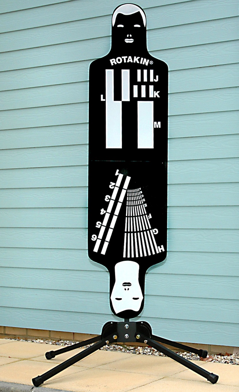
The security industry has its own testing standard. The Rotakin target was developed by HOSDB (Home Office Scientific Development Branch) as a means of auditing the efficiency of a CCTV system. It consists of a human silhouette target 1.6m in height. When the target fills the screen vertically it is said to be 100%R.
The target has various gratings for ensuring the modulation transfer function of the system allows footage to have the required resolution so that video material will stand up in court.
As well as lens, sensor, encoding/compression system the other factor that will affect how well each resolution grating is reproduced is lighting.
The requirement for identification is that the subject more than fills the frame (i.e. 120% R).At 100% R the A-grating should be discernible which implies the system has 500TVL resolution.

Thursday, March 08, 2012

What's in your rucksack?


Phil and High go over the basic set of tools and test kit that broadcast engineers on the hoof need! Find it on iTunes, vanilla RSS, YouTube or the show notes website.

Wednesday, September 14, 2011

Things that peaked my interest at IBC

I spent just a couple of days over at the RAI in Amsterdam. It was splendid to catch up with some old pals and Bryant Broadcast do an excellent night out. My main observation is that 3D/stereoscopic was no where near as prominent as it was last year and as the number of network delivery solutions increases the number of 'proper' transmitter companies seems to drop.

Newtek - updates to TriCaster, new model & control panel. The new 450 is very similar to the 850 but has only four HD inputs (against eight). The other things that I think are significant;
  • 3Play - their "poor man's EVS" has been improved. Running on what looks like a Tricaster 850 chassis it now has eight inputs and can run two outputs simultaneously. For sports slow-mo it is an excellent quick turn-around solution at the fraction of the cost of EVS.
  • VTR-style control for the DDRs in Tricaster; might suite some people.
  • Tricaster Extreme upgrade - allows for eight ISO records (can be either cameras or other internal/external sources, at different rasters and codecs than the main record).
  • They fixed the AUX audio in embedded HD-SDi I'd been moaning about!
  • The network sources (iVGA feeds) can now carry audio as well.
VidCheck - file-based QC is getting good! In fact this one looks like it needs serious consideration! I have a demo license on the way and will report back. Along with being able to test all the usual codecs etc it does full ITU.1770 audio loudness AND has numerous correction facilities; Tektronix AND Eyeheight, you might say.
  • Containers: MPEG-2 TS, MPEG-2 PS, MXF, MP4, MOV, ASF, AVI, LXF, GXF, FLV, F4V
  • Formats: Web, SD, HD, D-Cinema and many custom formats
  • Video: MPEG-2, IMX, XDCAM, D10, HDV, DV25, DVCPro50, DVCPro100/HD, AVC/H.264, VC-1, ProRes, DNxHD/VC-3, MJPEG
  • Audio: MPEG, PCM, WAV, AAC, stereo, 5.1 / 7.1 Dolby, multiple different language tracks
The really significant thing is the price €5k with paid options (DolbyE, ProRes etc) in the hundreds rather than thousands of pound. It also seems to handle multi-core computers much better, a single instance scaling to 28 cores.

AutoQue - they make broadcast monitors, who would have thunk it? They seem to be pitching them very much against the JVC DT-V24 series at the bottom end (a grand cheaper) and the VuTrix at the edit suite/grade-1 end (again, a lot cheaper). I have demo stock coming so I will write a bit more when I've seen them.

Other things worthy of note - Tek now have all their 3D analysis tools in the WVR/WFM-8000 series 'scopes. I had a very informative half-hour with Lee Ballinger from Tektronix going over them.

Thursday, June 02, 2011

Tektronix WVR5200

During a manic day I was fortunate enough to bump into my old Tektronix mucker Tom Perry who had a new WVR5200 in his rucksack and gave me a quick in-the-street demo! It seems like a much more complete instrument than the current WVR5000 'scope and I can't believe it won't cannibalize their WVR7000 and 8000-series business. The things that stood out for me are:
  • Much improved four-tile monitoring with four inputs that can be configured as 4 x SDi (270M, 1.48G, or 3G - yes!) or 2 x dual-link. With four discrete inputs you can display all four at once.
  • An SDi o/p that can be any of the inputs OR a test output with bars or pathological signal.
  • Audio loudness - and up to 16 channels via embedded groups
  • Full Java control (the 5000 lacked this)


So I think this is excellent - the only thing missing is physical layer measurements. Some of the better features are paid-for upgrades (license key) but at £4.5k this represents superb value.
I shall write more when I've had one in to evaluate.